
Implementation and first application of EMC3-EIRENE on DTT for assessing the heat load on the ICRH antenna
Source: arXiv:2607.23528 · Published 2026-07-26 · By H. S. Wu, Y. Feng, F. Subba, S. Ceccuzzi, P. Innocente, M. M. Robaldo et al.
TL;DR
This paper presents the implementation and initial application of the 3D edge plasma transport code EMC3-EIRENE on the Divertor Tokamak Test (DTT) facility, focusing on assessing the heat load on Ion Cyclotron Resonance Heating (ICRH) antenna surfaces. To validate the modeling setup, the authors first simulate axisymmetric plasma conditions and benchmark EMC3-EIRENE against the established 2D edge code SOLPS-ITER, achieving good agreement in plasma profiles and heat flux. Next, the actual 3D antenna geometry is incorporated in simulations, enabling evaluation of the spatial distribution and peak values of heat loads on antenna components, which reach up to 3.8 MW/m² on the side plate surfaces. The study further explores the impact of toroidal antenna symmetry, cross-field transport coefficients, and 3D gas puffing on heat loads, showing increased heat fluxes and significant localized plasma density variations associated with the antenna structure and particle sources. These results provide critical input for antenna design and cooling system optimization. This work represents the first application of EMC3-EIRENE to DTT and offers a workflow for self-consistent 3D edge plasma modeling including complex antenna geometry and operational scenarios.
Key findings
- EMC3-EIRENE reproduces axisymmetric plasma profiles within 20% difference compared to SOLPS-ITER benchmarks for electron density and within 15% for parallel heat and particle flux at the outer target (Fig 2).
- Peak heat loads on the ICRH antenna surfaces reach up to 0.9 MW/m² on the top plate, 2.1 MW/m² on side plate 1, and 3.8 MW/m² on side plate 2 in 3D simulations assuming single antenna toroidal symmetry (Fig 7).
- Scan of antenna toroidal symmetry shows peak heat loads increase as symmetry decreases (i.e., fewer toroidal repetitions), with less than 10% difference between 1 and 3 toroidal zones while saving >3x computational time (Fig 5 and 6).
- Cross-field transport coefficient D⊥ scanned from 0.1 to 0.5 m²/s leads to an order of magnitude increase in density at the antenna front plate and heat loads rising from ~2-4 MW/m² to 10-40 MW/m² (Fig 10 and 11).
- The heat load asymmetry between the two side plates is linked primarily to local magnetic field tilting angles and antenna geometry, with plate 2 receiving nearly double the parallel heat flux of plate 1 (Fig 11b).
- 3D gas puffing near the antenna increases peak heat loads by 2-3x due to enhanced local plasma density from neutral ionization, with heat load patterns sensitive to puffing position along toroidal and vertical directions (Fig 13-16).
- The plasma density near the antenna develops a ‘belt’-like low-density structure in the far Scrape-Off Layer (SOL) region caused by antenna limiting effects on plasma transport (Fig 8).
- EMC3-EIRENE’s flexible 3D grid allows simulating complex geometry effects and reduces reliance on 2D axisymmetry assumptions that may not hold near protruding structures.
Threat model
n/a — The paper addresses physical plasma-material interaction modeling in a fusion device; no digital security adversary or cyber-threat model is considered.
Methodology — deep read
The authors implement the coupled EMC3 (3D fluid plasma transport) and EIRENE (neutral particle transport Monte Carlo) code suite on the DTT tokamak geometry to model edge plasma and antenna heat loads.
The threat model is physical plasma interaction with antenna structures protruding into the SOL, but no security adversary is considered.
Data used include magnetic equilibria and geometric descriptions from DTT baseline configuration, with core plasma boundary conditions derived from prior SOLPS-ITER simulations. The computational domain includes the core boundary, SOL, divertor, and antenna surfaces.
Pre-processing involves identifying magnetic topology (X-point, O-point) and extracting geometry for mesh generation. A two-dimensional orthogonal plasma grid aligned with flux surfaces is generated for the base plasma domain. For 3D, magnetic field line tracing extends the 2D grid toroidally to form a 3D structured plasma grid. The neutral gas grid is created independently with high geometric flexibility to model the antenna protrusions.
The antenna is modeled geometrically as a box-shaped object with a shaped plasma-facing front plate matching real antenna contours and sharp edges elsewhere to focus on peak heat flux estimation.
The core and SOL plasma is modeled by EMC3 fluid equations coupled with neutral particle transport via EIRENE using Monte Carlo methods.
Simulations are run with fixed perpendicular transport coefficients (D⊥ and thermal conductivity χ⊥), varied in a parametric study. Plasma parameters including density, temperature, and heat fluxes are calculated self-consistently. Sheath boundary conditions with given heat transmission coefficients are applied at plasma-material interfaces.
A benchmark is performed first under axisymmetric conditions without antenna geometry by comparing to SOLPS-ITER in electron density, temperature, parallel heat and particle flux profiles at outer midplane and divertor targets. Good agreement within 15-20% confirms correct setup.
For antenna heat load studies, different levels of toroidal symmetry (1,3,5,15 repetitions) representing different antenna numbers and computational domains are run to assess 3D effects versus computational cost.
A parametric scan over D⊥=0.1-0.5 m²/s explores sensitivity of density decays lengths and heat loads. Additionally, 3D localized deuterium gas puffing sources at various poloidal, toroidal locations with fixed rates are included to study neutral fueling and ionization impact on plasma and heat loads.
Evaluations are performed mainly by analyzing spatial distributions and peak values of heat flux on antenna plates, electron density patterns near antenna geometry, and CPU runtimes per iteration normalized to test particle counts.
Results include 1D profiles at outer midplane, 2D poloidal cross sections, and fully resolved 3D spatial distributions. Comparisons with baseline codes, parametric ablations, and 3D scan variations support quantitative conclusions.
The workflow including pre-processing, mesh generation, and post-processing is described but detailed numerical methods and code implementation are deferred for future publications. Code release and reproducibility are not explicitly stated. The antenna plasma domain is currently limited to near SOL without extending fully to the first wall.
Example end-to-end: Starting from magnetic equilibria and antenna CAD data, a 3D plasma grid is generated by tracing field lines from the 2D flux-aligned base grid. The antenna geometry is embedded, imposing exclusion where plasma cannot exist. The coupled EMC3 plasma solver and EIRENE neutral Monte Carlo calculations run until convergence producing 3D distributions of plasma parameters. Heat fluxes on antenna plates are computed including sheath transmission and recombination contributions. Post-processed results show strongly localized heat load spots on antenna side plates with maxima of 3.8 MW/m², with plasma density ‘belt’ formation in far SOL near structure. Computational cost scales linearly with toroidal domain size. Parametric variations reveal one order of magnitude impact of perpendicular transport on peak heat loads.
Technical innovations
- First implementation of EMC3-EIRENE 3D edge plasma transport code on the DTT tokamak facility specific geometry.
- Incorporation of realistic 3D ICRH antenna geometry into EMC3-EIRENE plasma-neutral simulations to predict localized heat loads on plasma-facing antenna surfaces.
- Use of toroidal symmetry scanning in EMC3-EIRENE allowing flexible trade-off between modeling accuracy and computational cost.
- Numerical analysis coupling 3D gas puffing sources with antenna geometry to investigate their combined influence on plasma behavior and antenna heat flux.
- Establishment of a workflow enabling generation and use of non-axisymmetric 3D plasma and neutral grids aligned with magnetic field topology and antenna structures.
Datasets
- DTT baseline equilibrium and geometry — N/A — proprietary tokamak data from DTT facility design
- SOLPS-ITER simulation data for benchmarking — limited size, publicly referenced from published literature
Baselines vs proposed
- SOLPS-ITER (2D axisymmetric): electron density ne profile at outer midplane — values within 20% of EMC3-EIRENE
- SOLPS-ITER: electron temperature Te profile at outer midplane — nearly identical to EMC3-EIRENE
- SOLPS-ITER: parallel particle flux Γ|| and heat flux q|| at outer target — peak difference approximately 15% compared to EMC3-EIRENE
- EMC3-EIRENE antenna heat load peak values on side plate2: 3.8 MW/m² vs top plate 0.9 MW/m² indicating strong spatial variation
- Toroidal symmetry=1 vs symmetry=3: peak heat load difference <10% while CPU runtime roughly triples going from 1/3 toroidal domain to full
Figures from the paper
Figures are reproduced from the source paper for academic discussion. Original copyright: the paper authors. See arXiv:2607.23528.
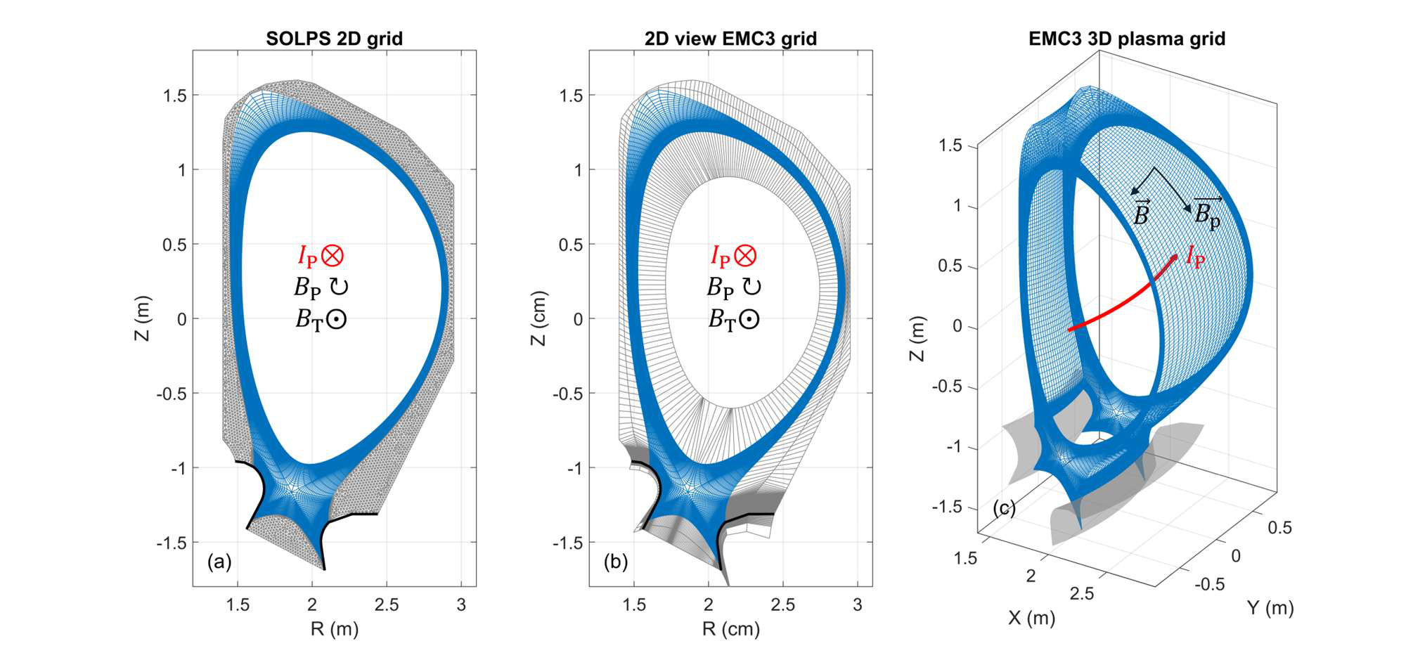
Fig 1: (a) SOLPS-ITER 2D computational grid; (b) 2D poloidal cross-section view of EMC3-EIRENE 3D computational grid at
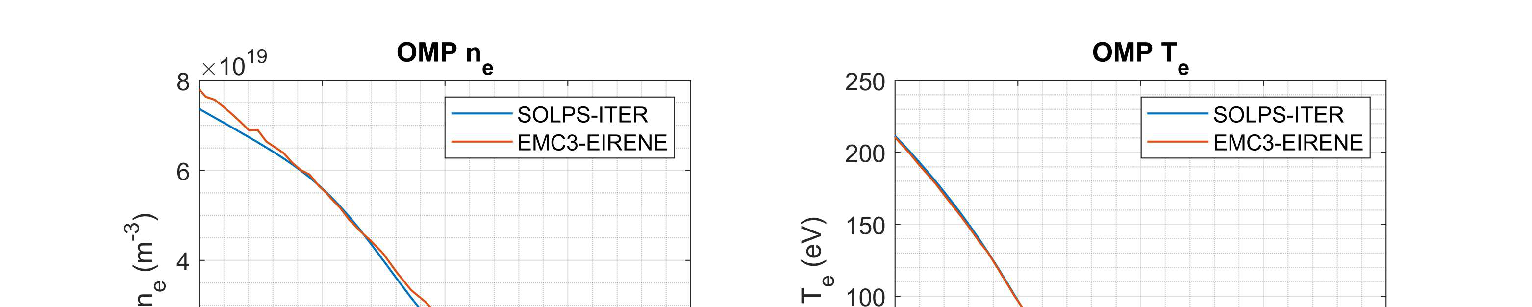
Fig 2: Comparison of plasma profiles between SOLPS-ITER and EMC3-EIRENE. (a) Electron density ne profiles at the Outer
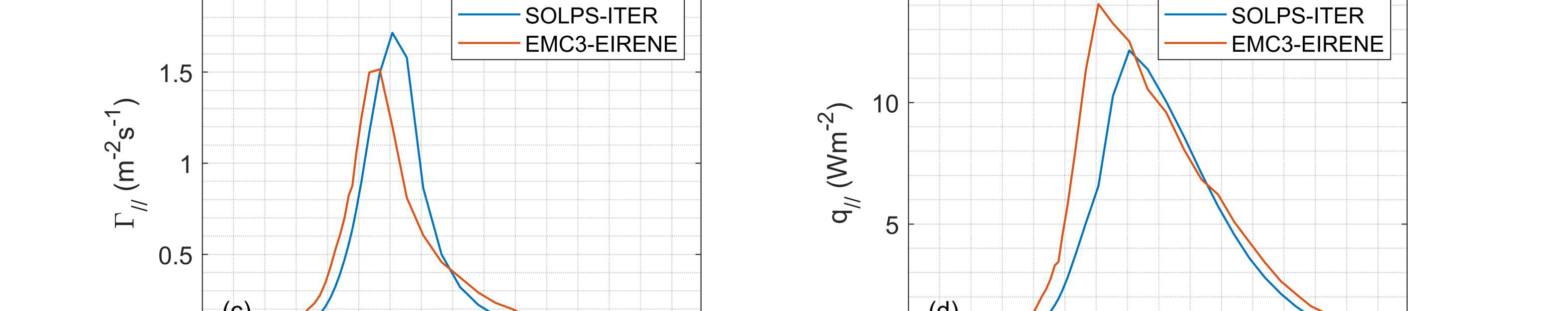
Fig 3: Comparison of plasma distributions between SOLPS-ITER and EMC3-EIRENE. (a) SOLPS-ITER 2D electron density ne
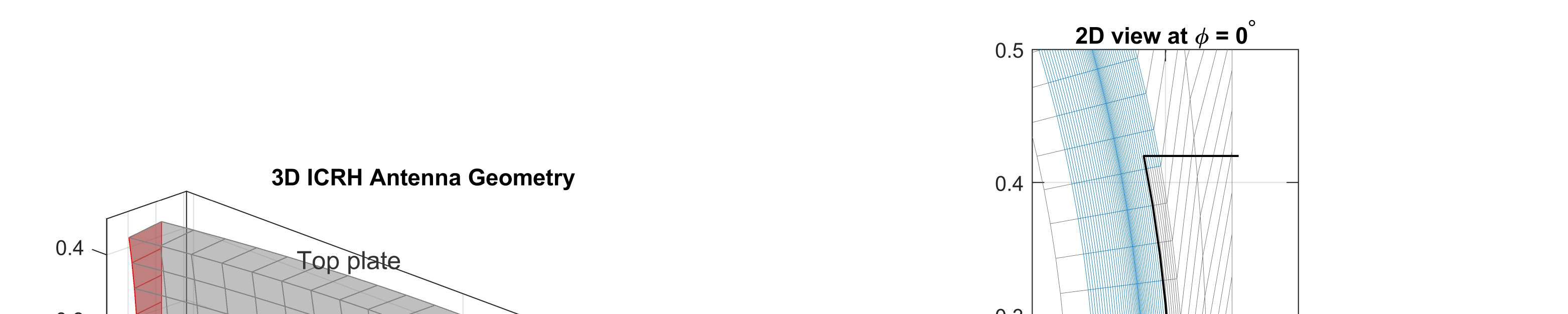
Fig 4: (a) 3D view of the antenna geometrical structure, consisting of the top plate, front plate, side plate 1 (blue) at φ=-10.2°
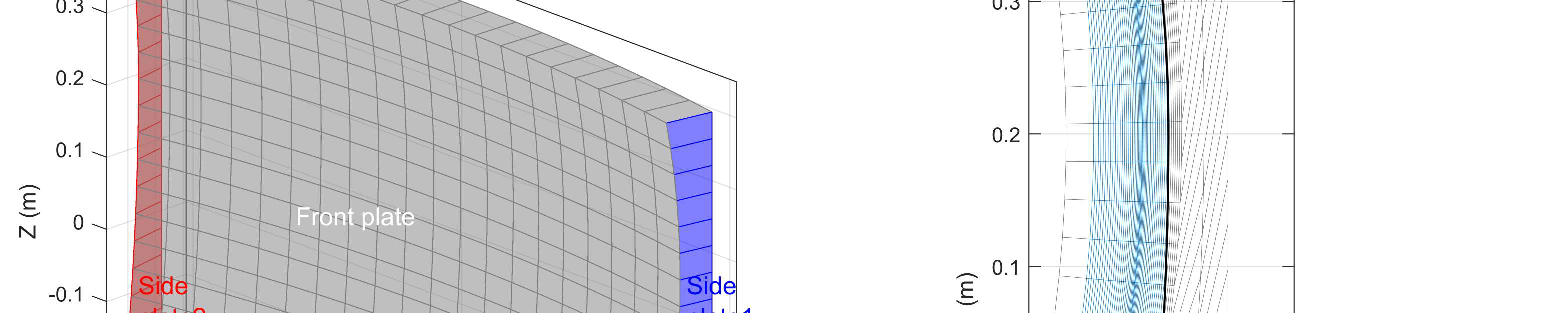
Fig 5: The parametric scan of antenna toroidal symmetry: the peak values of antenna heat load at top and two side plates
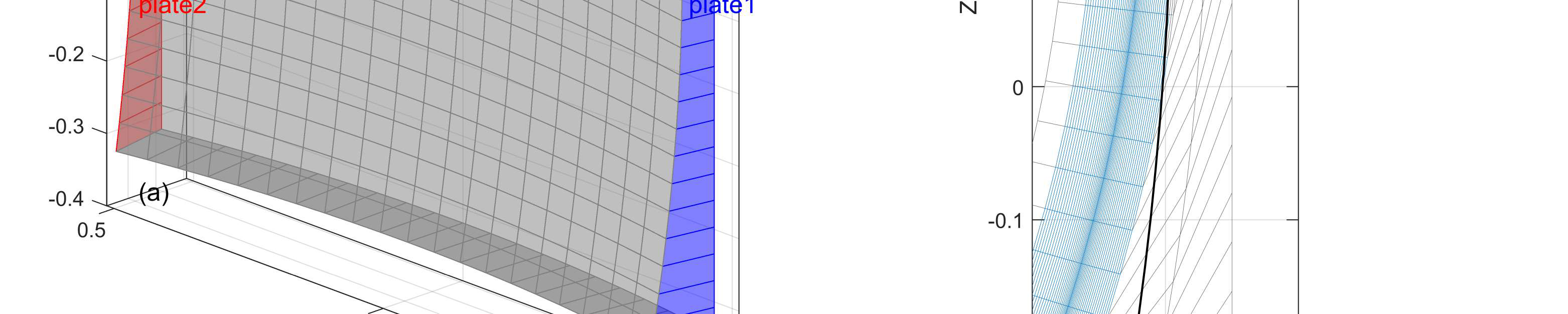
Fig 6: CPU-time used for one iteration per 10,000 test particles.

Fig 7: ICRH Antenna 3D heat load distribution from diƯerent viewpoints: (a) view for side plate1 and (b) view for side plate2.

Fig 8: Plasma density distributions for the antenna toroidal symmetry=1 case. (a) 3D view; (b) zoomed-in view near the
Limitations
- The plasma computational domain does not yet fully extend to the first wall; antenna structure modeling may be incomplete, limiting direct comparison to experiments.
- Cross-field transport coefficients are assumed spatially constant and fixed; real turbulent or neoclassical transport variations are not included.
- Impurity seeding and molecular recombination effects are not modeled, leading to conservative upper-bound heat load estimates.
- No inclusion of plasma drifts or currents; ion density equals electron density assumption may limit physical realism.
- Benchmarking is limited to stationary plasma conditions without transient or perturbative scenarios.
- The cause for the observed disproportionate heat load ratio between side and front plates relative to their toroidal widths remains unexplained.
- No experimental validation on DTT data yet available as the device is under construction.
Open questions / follow-ons
- How does impurity seeding and radiation impact modify the 3D heat load distribution predicted here?
- What are the transient plasma response and heat load dynamics during varying ICRH power and gas puffing scenarios?
- How do plasma drifts, currents, and electromagnetic effects alter the localized plasma parameters and heat flux?
- Can the disproportionate heat load ratio on antenna side plates relative to their surface area be explained via detailed sheath or local plasma physics?
Why it matters for bot defense
While the paper does not address CAPTCHA or bot-defense directly, the detailed 3D simulation techniques and computational trade-offs demonstrated are highly relevant to practitioners modeling complex spatial interactions under constrained computational budgets. The approach of trading off domain symmetry to speed up simulations while monitoring accuracy loss is analogous to strategies in ML model simplifications or spatially-aware detection systems.
Moreover, the coupling of 3D geometry, stochastic Monte Carlo methods, and parametric studies resonates with robust bot detection efforts where spatial or temporal variations complicate modeling. Bot-defense engineers can learn from the careful benchmarking, error quantification, and modular simulation workflow established here to better model adversarial behaviors with geometric or situational complexity. Finally, the study highlights that approximations assuming axisymmetry (or stationarity) may miss critical localized effects — a lesson applicable when designing bot detection systems relying on overly simplified assumptions about interaction patterns.
Cite
@article{arxiv2607_23528,
  title={ Implementation and first application of EMC3-EIRENE on DTT for assessing the heat load on the ICRH antenna },
  author={ H. S. Wu and Y. Feng and F. Subba and S. Ceccuzzi and P. Innocente and M. M. Robaldo and A. A. Tuccillo and R. Zanino },
  journal={arXiv preprint arXiv:2607.23528},
  year={ 2026 },
  url={https://arxiv.org/abs/2607.23528}
}