
An overview of stray light findings and interpretation during on-sky commissioning of LSSTCam
Source: arXiv:2606.31945 · Published 2026-06-30 · By Gabriele Rodeghiero, Alex Drlica-Wagner, Alessio Taranto, Luca Rosignoli, Hannah Pollek, Aashay Pai et al.
TL;DR
The paper addresses the pervasive challenge of stray and scattered light contamination in wide-field astronomical telescopes by presenting an in-depth overview of the stray light investigations conducted during the on-sky commissioning of the LSST Camera (LSSTCam) at the Vera C. Rubin Observatory. It highlights how stray light artifacts arise from complex optical and mechanical interactions within the compact three-mirror Simonyi Survey Telescope design and shows the difficulty of shielding such a system from bright off-axis sources like the Moon, bright stars, and the dome environment. The study documents the comprehensive empirical and simulation-based approach taken by the commissioning team to detect, characterize, model, and mitigate stray light through observational campaigns, advanced ray-tracing simulations, and iterative engineering adjustments. The work builds on prior stray light studies but extends them with real on-sky data, identifying unexpected stray light pathways and providing a detailed catalog of stray light features encountered during early operations.
The results demonstrate how the combination of on-sky targeted stray light tests, in-dome calibration using pinhole and collimated beam projectors, and non-sequential ray-tracing simulations using detailed CAD models enabled the identification of key stray light sources and their optical paths. Several mitigation strategies, including mechanical baffling, coatings, and scheduling constraints, were proposed or implemented. Notably, the absence of the Light Wind Screen (LWS) during commissioning was found to increase stray light contamination, highlighting the importance of this component. The authors convey that the complex and varied stray light features observed during commissioning provide valuable lessons for future wide and extremely wide-field telescope designs, especially those seeking low surface brightness sensitivity.
Key findings
- LSSTCam commissioning identified a range of stray light features correlating with off-axis bright sources such as stars (mag < 2), planets, and the Moon, with >116,000 images visually inspected to catalog these phenomena.
- Early stray light modeling predicted three main angular regimes where stray light dominates: 3°–5° from scattering between LSSTCam lenses L1 and L2; 6°–12° from direct M3 reflections bypassing M1 and M2; and 12°–30° from direct M1 bypass paths hitting internal camera structures.
- Ray-tracing simulations in Ansys Zemax OpticStudio® non-sequential mode successfully reproduced many, but not all, stray light arc patterns observed on-sky (Fig. 3, Fig. 8).
- Calibration with a Collimated Beam Projector quantified off-axis scatter from the M2 baffle and refined the angular visibility of a specific 'scratched tape' stray light artifact (Section 3.3.1, 3.3.3).
- The LWS, designed to restrict off-axis stray light beyond ~20°, was not installed during commissioning, resulting in elevated levels of stray light that are expected to reduce upon its completion (Section 1.1).
- Pinhole (stenopeic) imaging revealed specific stray light leaks including illumination from M1 direct paths, holes in the Top End Assembly baffles, and reflections off the L1 purge ring (Fig. 6).
- The unique compact M1M3 mirror cell and limited baffle insertion options due to fast f/1.2 optics contribute significantly to stray light challenges.
- Difference Imaging Analysis (DIA) was effective at isolating faint transient stray light features by removing static sky backgrounds (Fig. 5).
Threat model
The adversary in this context is unwanted stray and scattered light entering the LSSTCam from bright off-axis astronomical sources (bright stars, planets, Moon) or interior dome lights that follow unintended optical or mechanical paths, contaminating science images. The adversary cannot physically alter the telescope or camera hardware during commissioning but may affect data quality by appearing in observations due to telescope pointing or environmental conditions. The threat excludes deliberate sabotage or hardware tampering.
Methodology — deep read
Threat Model & Assumptions: The threat consists of stray and scattered photons originating from bright astronomical objects (stars, planets, Moon) or interior dome light paths that enter the camera focal plane via unintended optical or mechanical paths. The commissioning team assumed on-sky sources and dome geometry vulnerable to stray light propagation, with an adversarial environment consisting of bright off-axis light sources contaminating scientific data. The physical assumptions included single-scatter dominance and neglect of higher-order scattering for initial analyses, although later ray tracing incorporated complex multi-bounce paths. The adversary cannot physically change hardware during commissioning but can affect observation scheduling and pointing.
Data: Over >116,000 LSSTCam images from on-sky commissioning (Apr–Sep 2025) were visually inspected along with ∼14 hours of on-sky stray light test observations and 19 hours of in-dome calibration tests including pinhole imaging and collimated beam projector exposures. Metadata from images (telescope pointing, dome slit position, Moon/stars location) was compiled to correlate stray light occurrences. ComCam data from 2024 with a smaller FoV was also analyzed for initial stray light characterization. No machine learning was applied, but difference imaging was used to isolate variable stray light features.
Architecture / Algorithm: The core technical method was non-sequential ray tracing simulations in Ansys Zemax OpticStudio, importing detailed CAD models (STEP, IGES formats) of the telescope optics, mechanical structures, LSSTCam internals, and dome elements. Optical coatings, surface roughness, and scattering parameters were assigned based on laboratory reflectometer measurements. Simulation workflows included tracing rays from sky sources forward to focal plane and backwards from focal plane to sky to identify stray light convergence zones and origin paths. The team used 'filter strings' in Zemax to isolate rays undergoing specific reflections and scatters. Additionally, specialized scripts produced macro files to encode off-axis source geometry for injecting into the Zemax models.
Training Regime: Not applicable as no machine learning training was done. However, commissioning tests were scripted and automated where possible, with test sequencing controlled via the Rubin Observatory LOVE system and Jira for tracking tasks and requirements. Scripts and simulation parameters were iterated based on image inspection feedback.
Evaluation Protocol: Stray light features were evaluated qualitatively via direct image inspection as well as quantitatively by comparing simulated ray bundles to observed artifact morphologies. Difference Imaging Analysis was used to isolate time-varying stray light elements. Multiple test cases with different off-axis angles and rotator positions were executed to identify angular dependence and reproducibility. Baseline expectations arose from the 2006 Photon Engineering FRED simulations, and new tests built upon them. Observational constraints such as limited telescope time and partial dome baffling (LWS absence) were noted.
Reproducibility: The methodology depends on proprietary CAD files and specialized Zemax software; no public code release or frozen weights exist. The extensive commissioning data remains internal to the collaboration and observatory. The tests and simulations described are not currently fully reproducible outside the Rubin project due to data and software access constraints.
Concrete Example End-to-End: For the 'scratched tape' stray light artifact observed, the team used on-sky bright star raster scans to detect the feature, correlated position angle and rotator clocking with stray light visibility, employed difference imaging to remove static sky features, then ran non-sequential Zemax ray tracing with CAD model subsets of internal baffles and camera optics, including measured reflectance for the tape region. The Collimated Beam Projector produced controlled light injection to confirm angular acceptance and scattering behaviors matching the observed stray light morphology. This triangulation pinpointed the physical origin and informed mitigation plans.
Overall, the methodology combined empirical image-based detection with physically accurate optical-mechanical modeling and calibration tools to understand and reduce stray light contamination in a state-of-the-art wide-field survey telescope system.
Technical innovations
- Use of non-sequential ray-tracing simulations in Ansys Zemax OpticStudio® combined with detailed CAD mechanical models to reproduce complex stray light paths inside a large wide-field optical system.
- Development of a hybrid stray light investigation methodology combining on-sky observations, in-dome calibration (pinhole imaging, Collimated Beam Projector), and advanced optical simulations to isolate and identify varied stray light features.
- Implementation of custom Python tools to calculate off-axis angles of bright sources and automatically generate Zemax macro files for systematic stray light ray tracing studies.
- Application of Difference Imaging Analysis (DIA) techniques, originally designed for transient detection, to isolate and study faint stray light features temporally associated with bright moving sources.
Datasets
- LSSTCam commissioning imaging dataset — >116,000 exposures — Vera C. Rubin Observatory (internal, non-public)
- ComCam stray light test images — ~0.5 deg² FoV — Vera C. Rubin Observatory (internal)
- In-dome stray light calibration data — ∼19 hours — Vera C. Rubin Observatory (internal)
Baselines vs proposed
- Photon Engineering 2006 FRED® stray light simulation: Predicted major stray light sources by angular regime vs Current Rubin commissioning Ansys Zemax simulations: Confirmed main paths but uncovered additional subtle scattered paths and artifacts
- LSST Difference Imaging Analysis approach: Static sky residuals removed allowing detection of moving stray light features that were not identifiable in standard imaging
- Collimated Beam Projector calibration: Quantified M2 baffle scattered light levels for various off-axis angles, refining model parameters beyond initial design simulations
Figures from the paper
Figures are reproduced from the source paper for academic discussion. Original copyright: the paper authors. See arXiv:2606.31945.
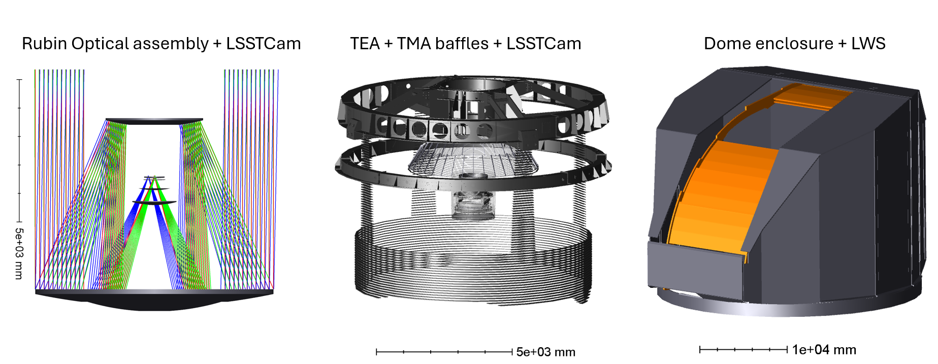
Fig 1: From left to right: optical assembly of Rubin with three powered mirrors, three lenses, and one curved
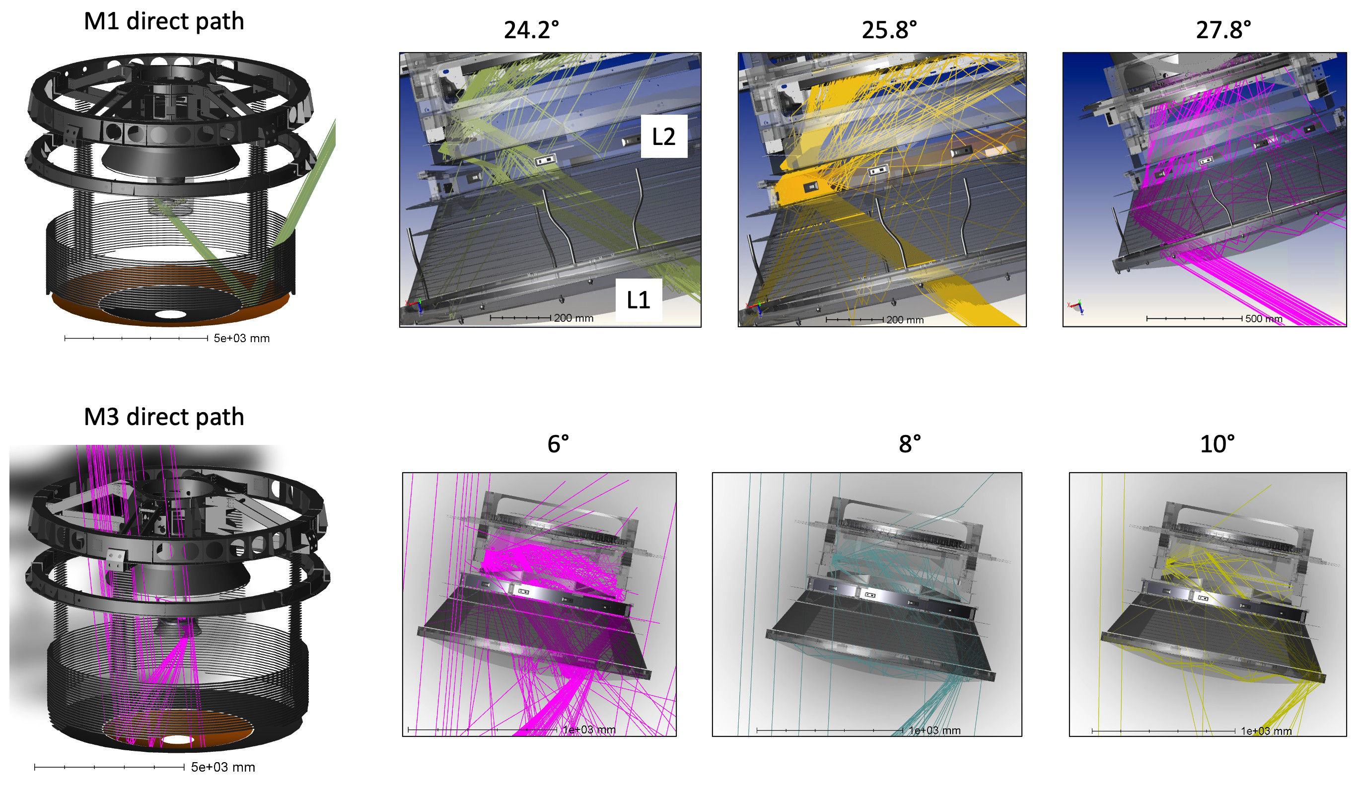
Fig 2: Non-sequential simulations in Ansys Zemax OpticStudio® showing the stray light bundle from the M1
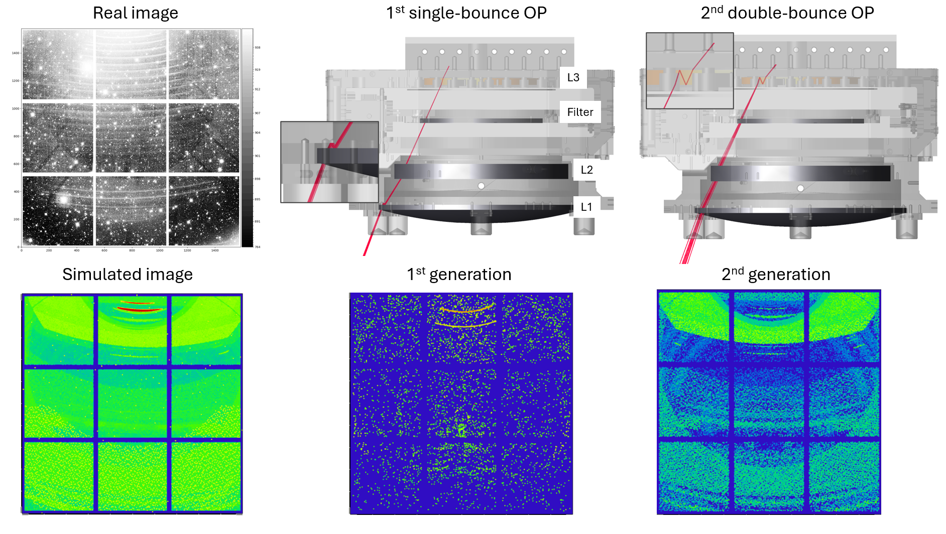
Fig 3: Top-left: Focal plane mosaic image acquired with ComCam during a dedicated stray light test using
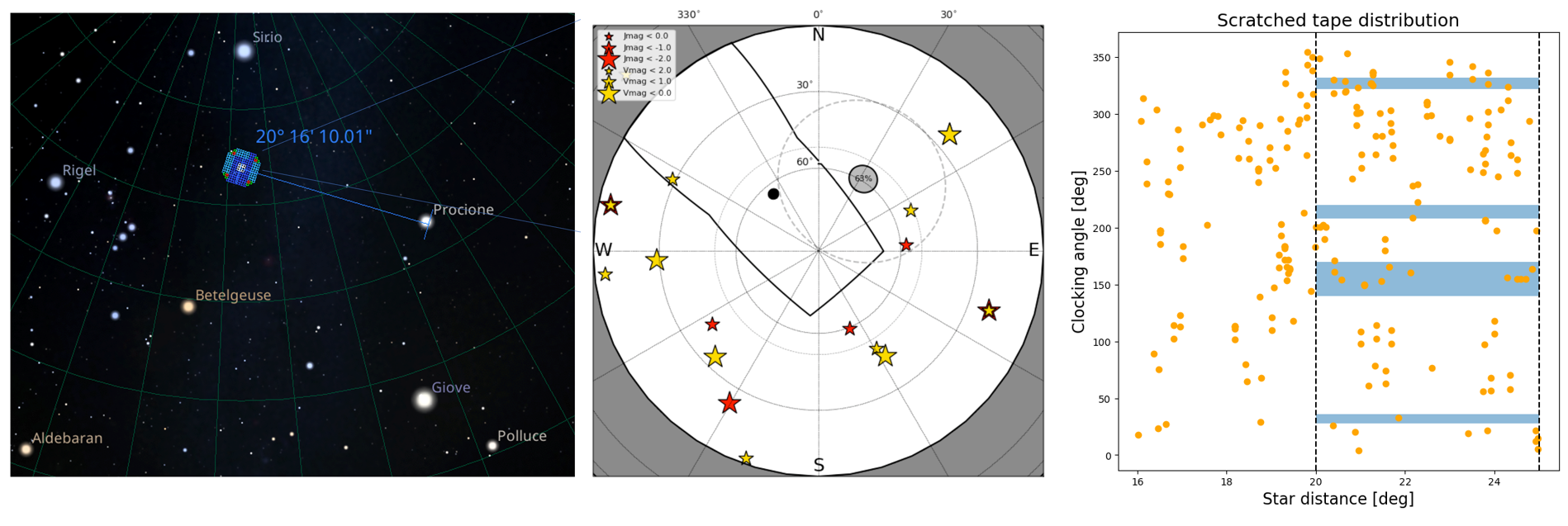
Fig 4: Examples of diagnostic figures for identifying stray light at Rubin Observatory. Left: Rubin-LSSTCam
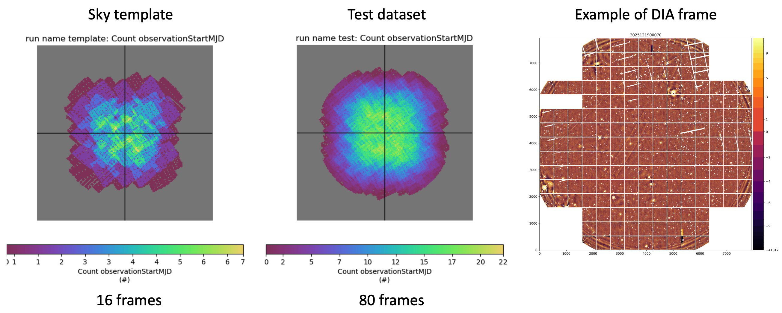
Fig 5: Difference Imaging Analysis (DIA) has been utilized for some stray light searches where the sky area
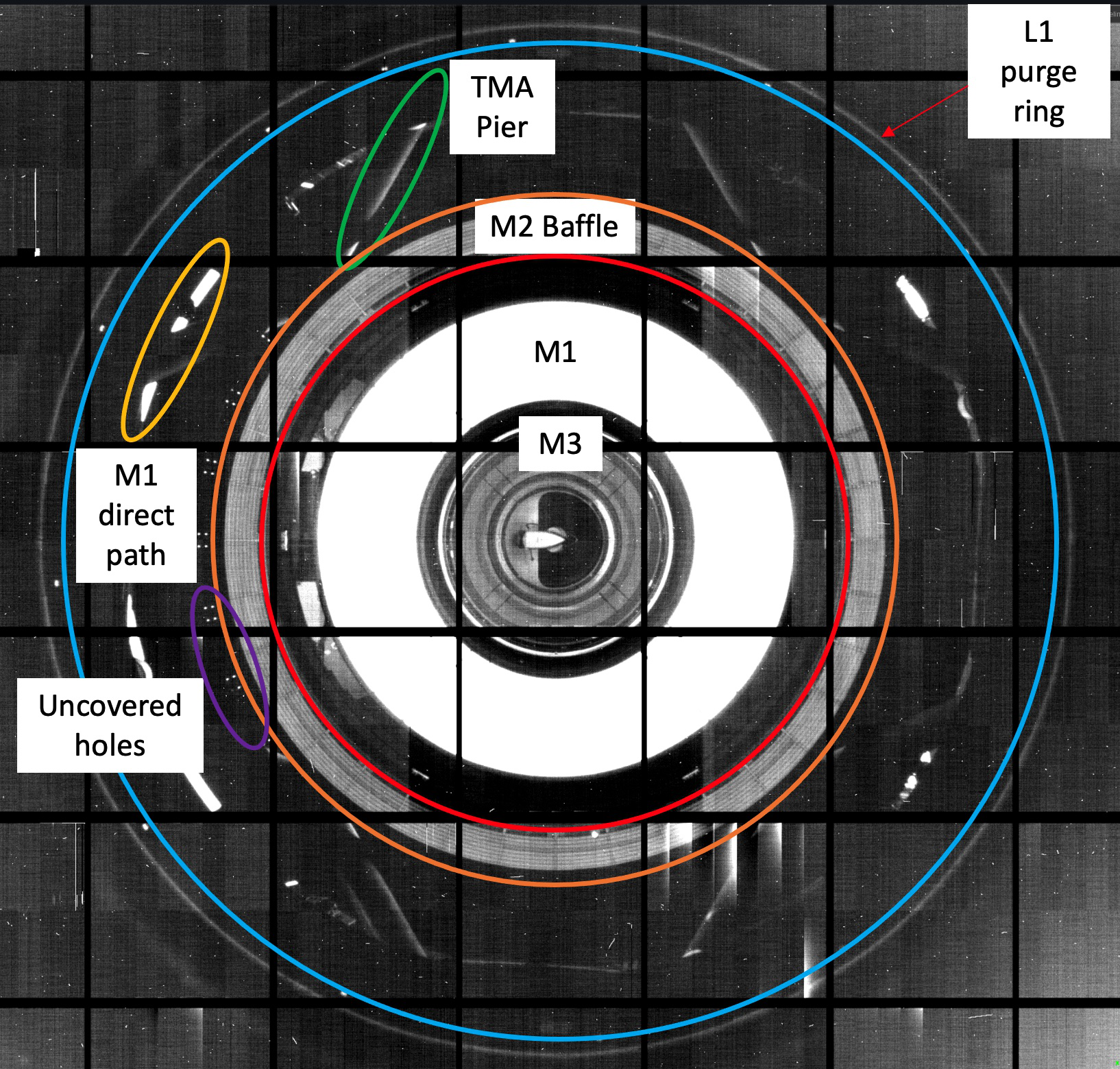
Fig 6: Image obtained during dawn twilight with the stenopeic (pinhole) technique for imaging the Rubin
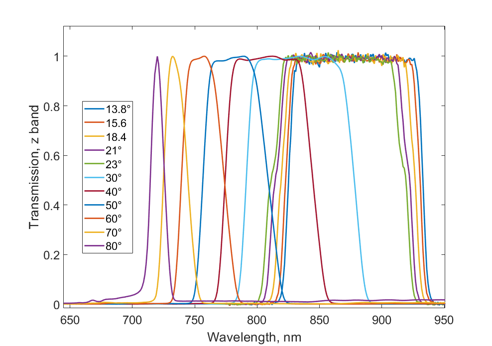
Fig 7: Example of filter transmission profile (z band) measured with the Cary 5000 spectrophotometer from
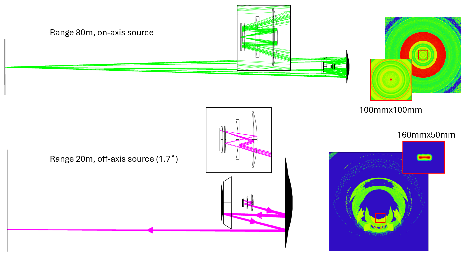
Fig 8: Top: Example of zones of convergence of the light beam found with the backward propagation path,
Limitations
- The commissioning period lacked a fully operational Light Wind Screen (LWS), causing elevated stray light that may not represent the final system performance.
- Ray-tracing simulations are computationally intensive and rely on partial CAD model selections, risking omission of some stray light contributors.
- Scattering and reflectance coefficients used in simulations are based on laboratory measurements but may not fully capture in-situ environmental variability or aging effects.
- No extensive adversarial evaluation was performed to simulate worst-case stray light scenarios beyond bright natural sources.
- Code and data used for stray light analyses are not publicly released, limiting external reproducibility and validation.
- Difference Imaging Analysis is limited to detecting variable or transient stray light features and may miss static but low-level stray light contamination.
Open questions / follow-ons
- How will stray light levels change with the installation and commissioning of the Light Wind Screen (LWS), and what residual stray light pathways will remain?
- Can more advanced coatings or dynamic baffling methods be developed to mitigate stray light without vignetting the wide field of view?
- How do environmental factors over long-term operations, such as dust accumulation and coating degradation, impact stray light characteristics?
- What automated analysis methods can be developed to systematically detect and classify stray light features in the voluminous LSST data stream?
Why it matters for bot defense
While primarily focused on optical instrumentation, this paper’s comprehensive stray light characterization and mitigation approach offers conceptual parallels to bot-detection and CAPTCHA systems where signal contamination by external or adversarial noise is a key challenge. Both domains require careful modeling of unintended input paths—optical or network—and the use of multifaceted diagnostics (observational data, simulations, empirical tests) to isolate sources of contamination. The combination of simulations with empirical measurements to validate and refine models can inform bot-defense strategies that blend behavioral analysis and system modeling. Furthermore, the principle of deploying physical and procedural 'baffles' to limit contamination echoes layered defenses in automated bot detection architectures. Bot-defense engineers could draw inspiration from the rigorous commissioning test protocols, targeted feature cataloging, and the iterative cycle of detection, modeling, and mitigation described here, tailored to their domain’s input and adversary characteristics.
Cite
@article{arxiv2606_31945,
  title={ An overview of stray light findings and interpretation during on-sky commissioning of LSSTCam },
  author={ Gabriele Rodeghiero and Alex Drlica-Wagner and Alessio Taranto and Luca Rosignoli and Hannah Pollek and Aashay Pai and Lynne Jones and Erin Howard and Sean MacBride and John Andrew and Douglas Neill and Travis Lange and Andrew Rasmussen and Aaron Roodman and Brian Johnson and Elana Urbach and Parker Fragelius and Eli Rykoff and Tomislav Vucina and Christopher Stubbs and Robert Lupton and Charles Claver and Joshua Meyers and Anastasia Alexov and Keith Bechtol and Lee Kelvin and Brian Stalder and Pierre Antilogus and Alexandre Boucaud and Aurelien Marini and Alexander Broughton and Leanne Guy and Tiago Ribeiro and Erik Dennihy and Bruno Quint and Aaron Watkins and Alysha Shugart and Lukas Eisert and Kevin Fanning and Marina Pavlovich and Yijung Kang and Hye Park and Paulo Lago and Kristopher Mortensen and Paulina Venegas Salas and Minhee Hyun and Karla Peña Ramírez and David Sanmartim and Shuang Liang and Gonzalo Aravena and Kshitija Kelkar and Kate Napier and Jacqueline Seron Navarrete and Carlos Morales Marín and Danica Žilková and Narayan Khadka and Eric Christensen and Yousuke Utsumi and Merlin Fisher-Levine and Yusra Alsayyad and Colin Slater and Fritz Müller and William O'Mullane and Enrico Giro and Rodolfo Canestrari and Guillem Homar Megias and Sandrine Thomas and Kevin Reil and Roberto Tighe and Mario Rivera and Juan Lopez and Claudio Araya Cortes and David Jiménez Mejías and Hernán Herrera and Freddy Muñoz Arancibia and Dimitri Buffat and Johan Bregeon and Jacques Sebag and Holger Drass and Pablo Zorzi and Massimo Brescia },
  journal={arXiv preprint arXiv:2606.31945},
  year={ 2026 },
  url={https://arxiv.org/abs/2606.31945}
}