
Autonomous Subsea Cable Search and Tracking with Graph-Optimised Priors and Visual Tracking
Source: arXiv:2606.23606 · Published 2026-06-22 · By Ibrahim Fadhil Djauhari, Adrian Bodenmann, Samuel Simmons, Cailei Liang, David White, Susan Gourvenec et al.
TL;DR
This paper addresses the challenge of autonomous subsea communication cable inspection using AUVs, where uncertainties in cable route maps, small cable diameters (∼27 mm), partial burial, and environmental conditions make continuous cable tracking difficult. The authors propose a novel framework that integrates graph-based optimization of an uncertain cable prior with real-time visual cable detection and tracking. The key innovation is the use of a physics-informed catenary model to bound search areas, reducing the search space to physically feasible regions around the cable route estimate. Visual detections drive graph updates and waypoint generation for cable following, and when tracking is lost due to missed detections or partial burial, a zig-zag search within the bounded envelope enables efficient recovery. Field trials with the Smarty200 AUV over a 120 m test cable section with deliberate offset errors demonstrated that the method updated the cable route consistently with observations and inspected up to 59% of visible cable, recovering after tracking loss.
Key findings
- Using graph-based optimization with visual observations reduces cable route uncertainty by aligning the cable prior to detected cable poses while preserving route smoothness (Fig. 5).
- The catenary-bounded search envelope constrains the lateral cable displacement in the search area to approximately 10% of the seafloor depth, improving search efficiency (σmax = 14.14 m with a 12 m depth).
- Real-time cable detection on board the Smarty200 AUV processes an image every 4.5 s on CPU (faster on GPU not implemented during trials) with a detection tile grid (N=3) used to determine observations from positive cable detections.
- Consecutive observation filtering requiring >3 detections within 2 m ensures robustness against false positives before updating graph edges.
- The AUV inspected up to approximately 59% of the visible 120 m cable length during tracking runs (using look-ahead distances Lwp between 6 - 12 m).
- The system recovered cable track successfully after deliberately imposed 7.5 m lateral offset in initial cable prior map.
- Search patterns adaptively expand from minimum σmin = 3 m (at last observed point) to maximum σmax = 14.14 m based on catenary profiles as distance from observation increases (Fig. 9).
- The graph optimization problem uses a Levenberg-Marquardt solver via g2o library with measurement uncertainties dominated by AUV localization errors (∼3 m).
Threat model
The adversary is environmental uncertainty and measurement noise rather than a malicious agent. Challenging factors include cable burial, uncertain prior route maps with up to 10% positional error, limited AUV sensor range, false positive and missed visual detections, and navigation errors (∼3 m). The system assumes no perfect knowledge of cable pose and cannot rely on features on the cable surface. It operates under normal oceanic physical constraints without intentional obstruction or interference.
Methodology — deep read
Threat Model & Assumptions: The adversary is not explicitly defined as this is an autonomous inspection problem, but challenges arise from environmental factors causing cable displacement (up to 5-10% of lay depth or several meters), partial burial, and false positive visual observations. The system assumes the cable route prior is uncertain but relatively accurate (offset ∼7.5 m in trials). The AUV has limited sensing range and navigation uncertainty (∼3 m), and the cable detection can suffer missed or false detections. The method must robustly handle these uncertainties to continuously track or efficiently search for subsea cables.
Data: Field trial data was collected using the University of Southampton's Smarty200 AUV, equipped with a downward-facing 12 M pixel camera capturing images at about 1 Hz while traversing a 120 m test cable in shallow (12 m) water. The cable was a 27 mm diameter decommissioned subsea communication cable laid in two sections (10 m and 100 m) with a 10 m gap simulating burial. Ground truth cable positions were recorded with acoustic transponders. Images were processed onboard for cable detection with no mention of labelled training data specifics here, but prior detector training used semi-supervised learning from previous work [15].
Architecture / Algorithm: The method has three components: cable search, cable following, and global cable route estimation.
- A cable-relative coordinate frame (with along-cable x_c and lateral y_c axes) is defined by linear regression on prior cable nodes to handle featureless cable matching.
- Cable detection is performed by a semi-supervised real-time classifier splitting images into NxN tiles (N=3 used), detecting cable presence.
- Consecutive cable detections generate cable observations (position + bearing) used to produce waypoints for visual tracking using a LOS controller with look-ahead distance Lwp.
- The cable prior is modeled as a graph of n evenly spaced nodes along x_c. Observations are associated to nearest graph nodes.
- Edges connect graph nodes enforcing spatial smoothness based on initial prior node distances, and measurement edges connect observations to nodes minimizing residual error.
- The graph optimization minimizes total error (sum of spatial and measurement errors weighted by their respective covariances), solved using Levenberg-Marquardt via g2o.
- Search areas are bounded by a physics-informed lateral catenary model based on cable physical parameters (diameter, density, lay tension, friction coefficients), providing realistic maximum lateral cable displacements.
- When tracking is lost, a zig-zag search is performed within the catenary-bounded envelope around the predicted cable.
Training Regime: The paper focuses on system integration and field validation rather than novel learning training. The cable detection method was pre-trained by semi-supervised learning in previous work [15]. Onboard processing during trials used saved weights and ran at ∼4.5 s per frame on CPU.
Evaluation Protocol: Multiple field dives were conducted (Table II) comparing the proposed tracking approach to a baseline lawnmower sweep. Metrics included inspection efficiency (percentage of visible cable nodes inspected), distance efficiency (ratio of cable length to AUV traveled distance), and overall survey efficiency (product of the two). The method was tested with deliberate 7.5 m offset errors in prior maps to simulate route uncertainty.
Reproducibility: The cable detection model and semi-supervised training is described in a prior publication [15], but the code and datasets are not explicitly stated as publicly released. The graph optimization uses g2o, an open-source library. The field trial dataset with the specific cable layout is proprietary from British Telecom Group and the trial setup is custom. Specific hyperparameters such as look-ahead distance (6-12 m), detection thresholds (dobs=2m, Nobs=3), and maximum search boundary (σmax=14.14m) are reported, aiding experimental replication.
End-to-end example: During a dive, the AUV starts with a prior route offset laterally by 7.5 m. At ∼0.2 m/s it captures images every ∼4.5 s, processing them with the classifier to detect cable sections in tiles. Consecutive detections exceeding spatial and temporal thresholds update graph observations. The graph optimization shifts the cable route nodes closer to observations while maintaining route smoothness. The system generates waypoints to follow the cable visually. If detections are lost (for example, if the cable is partially buried), a bounded search area derived from the catenary model defines lateral zig-zags until the cable is found again. This process iterates, continuously refining the cable route map and enabling robust inspection despite initial positional uncertainty and partial burial.
Technical innovations
- Graph-based optimization is inverted from typical SLAM: it refines the cable route map rather than the robot path to maintain a global cable estimate consistent with observations.
- Introduction of a cable-relative coordinate frame aligned along the approximate cable prior to correlate featureless cable observations to route positions.
- Physics-based catenary models used to dynamically bound the cable search region, limiting the search space to physically feasible cable deviations.
- Combination of semi-supervised real-time visual cable detection with graph optimization to enable simultaneous cable tracking and map updating onboard the AUV.
Datasets
- Field trial subsea cable dataset — 120 m cable length — British Telecom Group (proprietary)
Baselines vs proposed
- Dense lawnmower survey: inspection efficiency < tracking method (tracking achieved up to 59% coverage of visible cable; exact lawnmower baseline value not specified)
- Graph optimization prior correction: cable route median lateral error reduced from initial ∼7.5 m offset to near zero after graph updates
Figures from the paper
Figures are reproduced from the source paper for academic discussion. Original copyright: the paper authors. See arXiv:2606.23606.
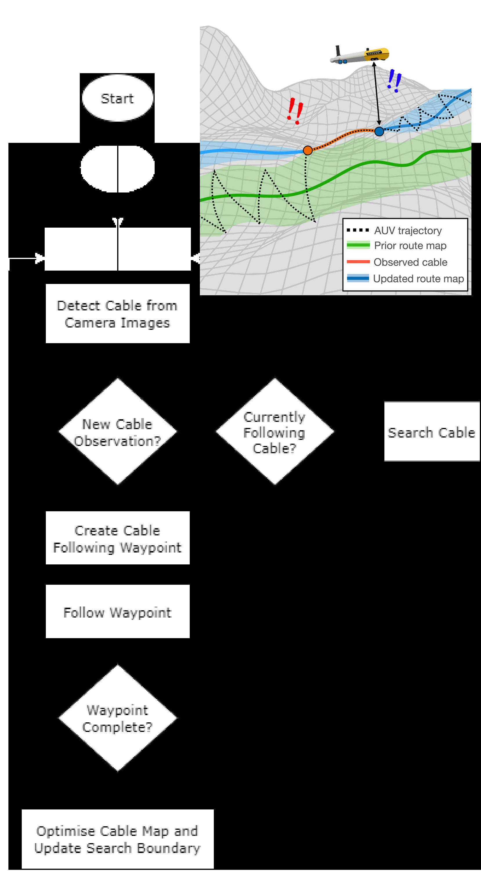
Fig 1: Flowchart illustrating the components of the cable tracking system.
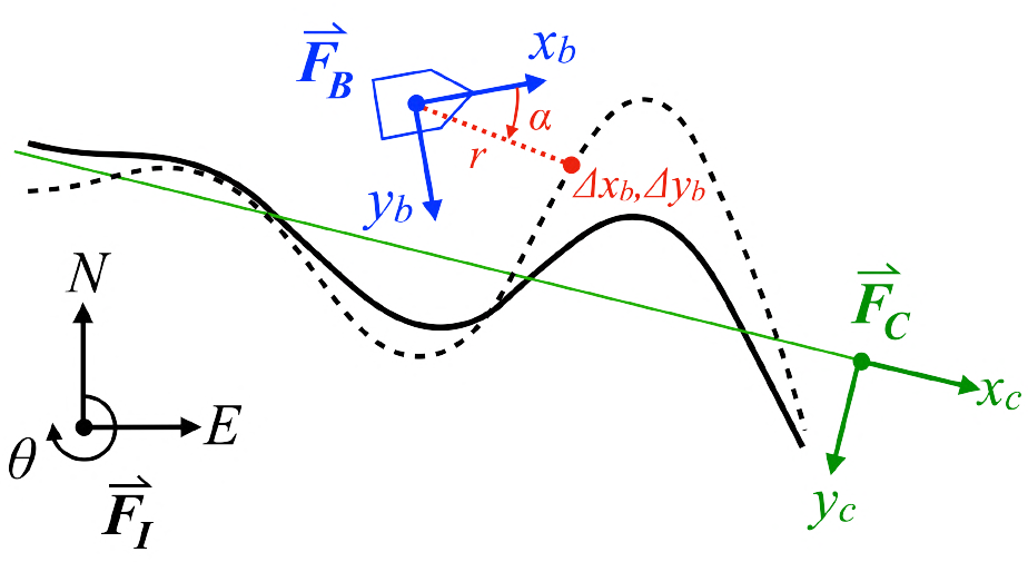
Fig 2: Illustration of the coordinate frames used in the subsea cable tracking
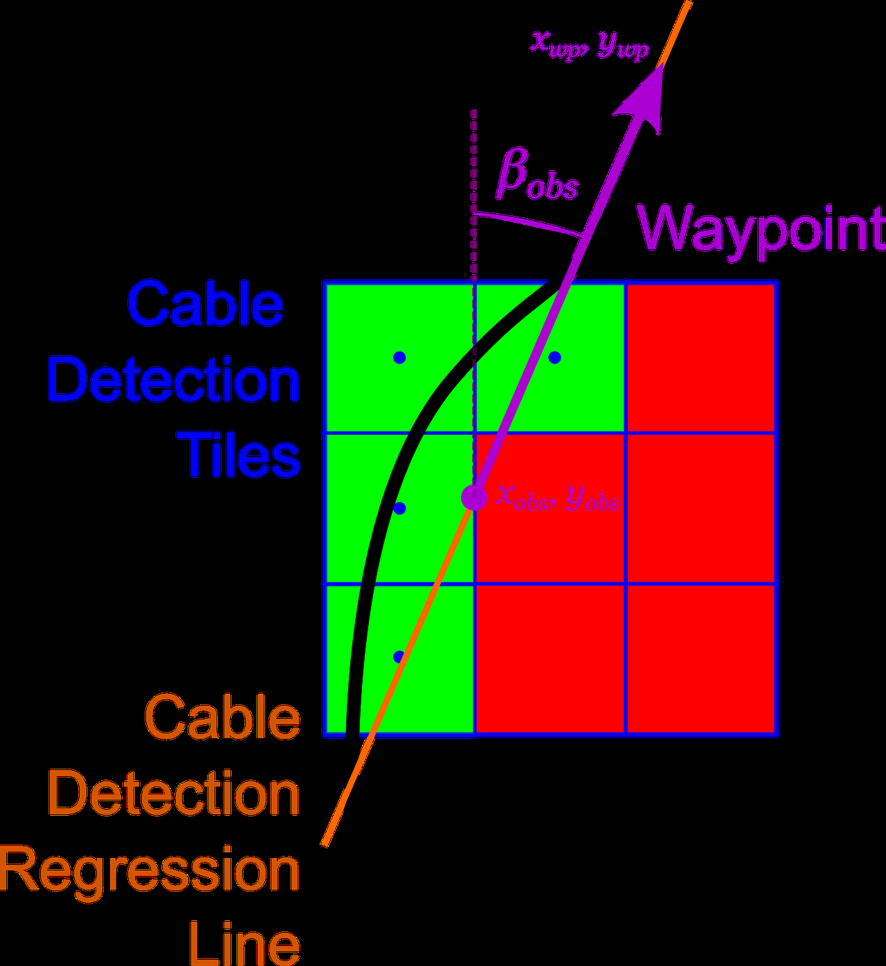
Fig 3: Illustration of 3 × 3 cable detection tiles. Green tiles indicate cable
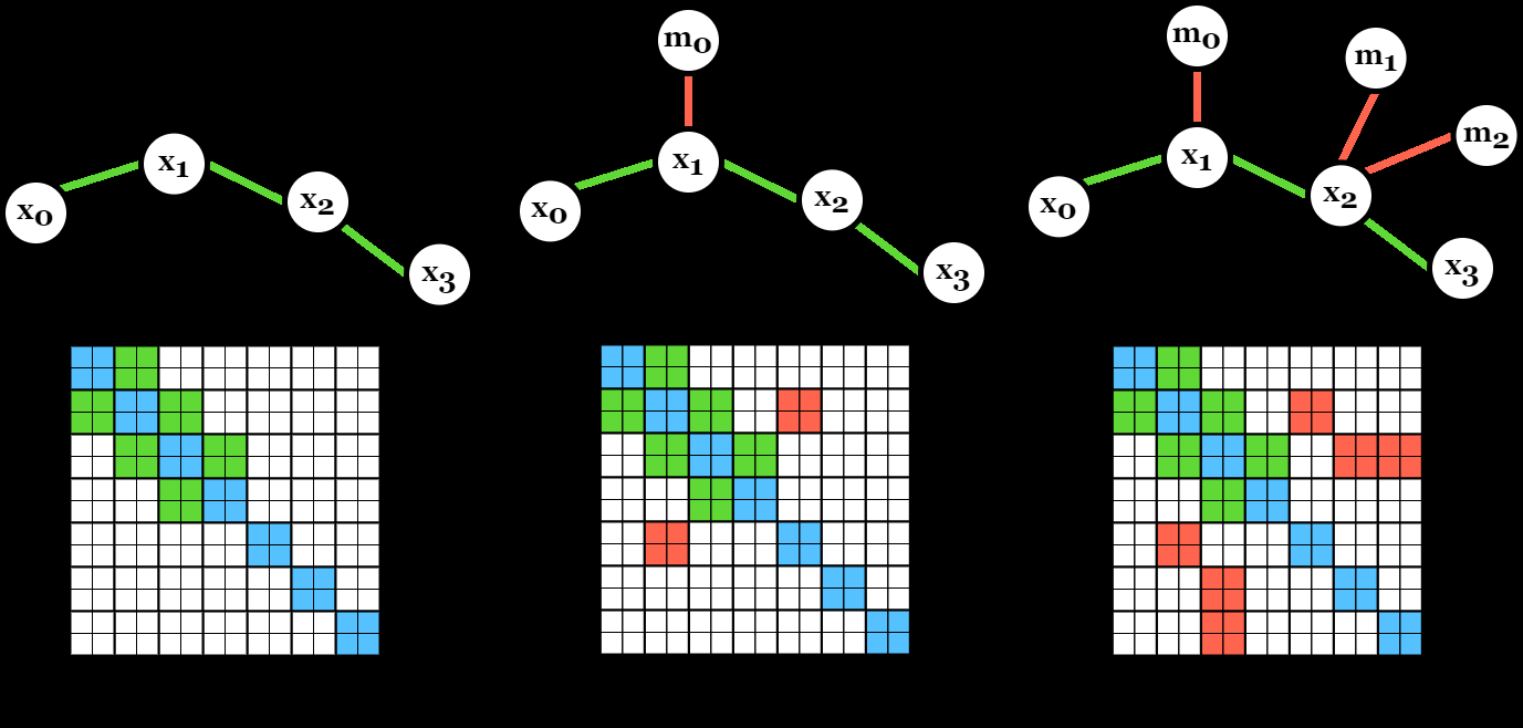
Fig 4: illustrates the front end graph construction of the [2(n+
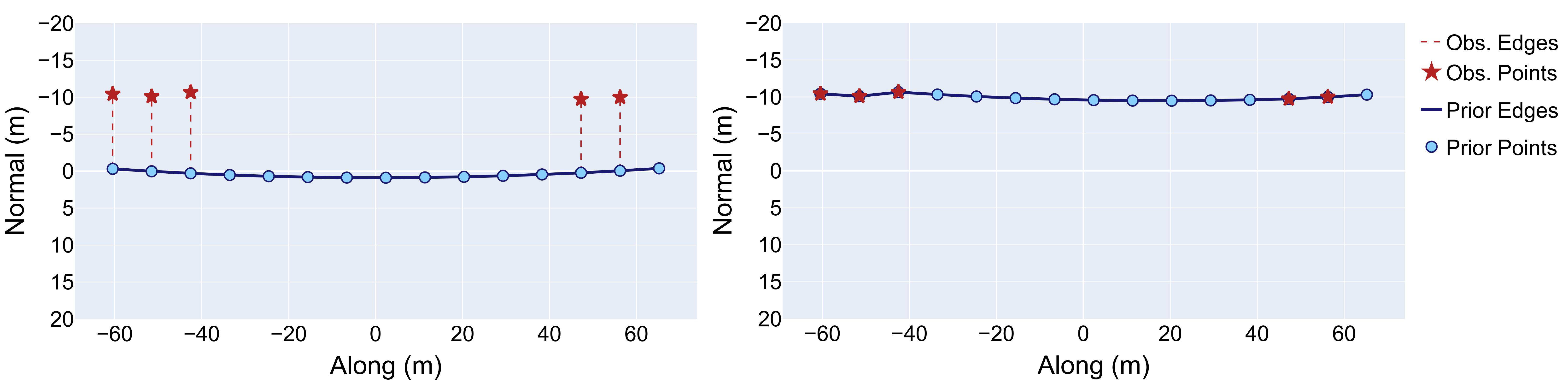
Fig 5: A cable route map shown before (left) and after (right) optimisa-
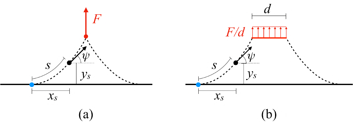
Fig 6: Top-down view of the cable lateral catenary (dotted line) resulting
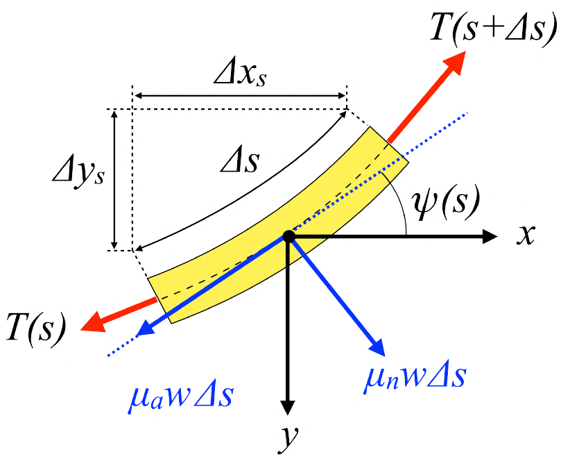
Fig 7: Plan view free-body diagram of a cable element. Friction between the
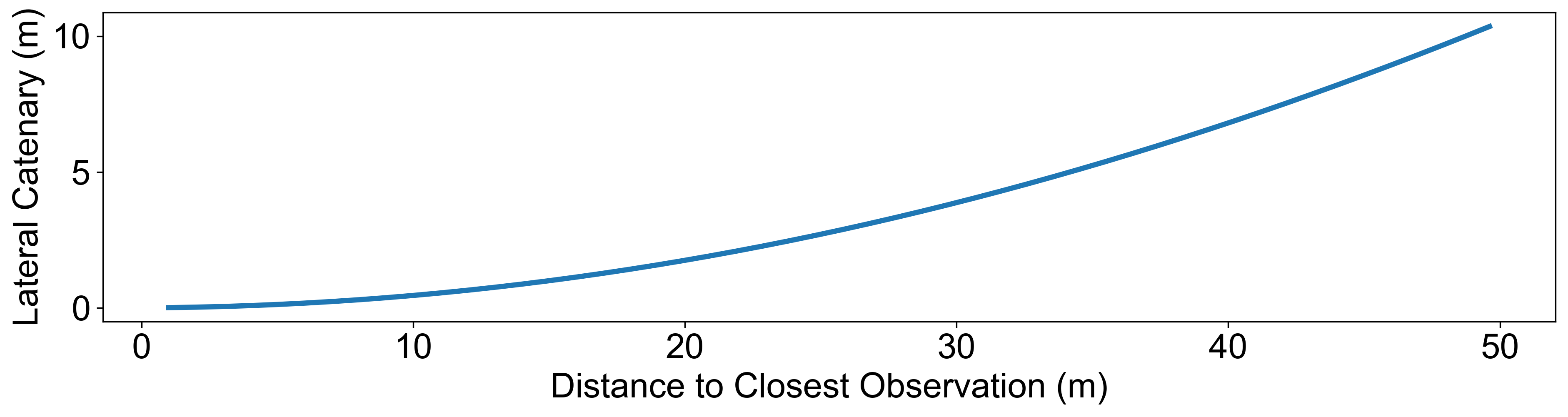
Fig 8: Search boundary curve for a subsea cable tracking mission with
Limitations
- The evaluation was on a short, shallow-depth cable (12 m depth, 120 m length), limiting insight into long-range deep-sea conditions.
- The cable detection method may produce false positives from linear seafloor features (such as anchor drag marks or sediment ridges) that satisfy consecutive observation criteria, potentially causing errors.
- Catenary model parameters (e.g., friction) are assumed constant and known, though sediment and cable conditions can vary significantly in real deployments.
- The approach assumes relative smoothness of cable route and no robot pose optimization within the graph, so localization errors directly affect mapping accuracy.
- Computational rate of detection processing (4.5 s per frame on CPU) could limit coverage speed; GPU acceleration was not implemented in trials.
- No explicit adversarial robustness testing or evaluation under harsh sea conditions or severe cable burial beyond the induced 10 m gap.
Open questions / follow-ons
- How scalable is the graph-based cable mapping approach for very long subsea cables (tens of kilometers), especially regarding computational efficiency and memory footprint?
- How robust is the visual detection and tracking system under more complex seabed conditions, turbidity, or in the presence of more frequent partial burial?
- Can the system be extended to incorporate multi-sensor data fusion (e.g., merging acoustic, electromagnetic sensing) to improve buried cable detection and tracking robustness?
- What are the effects of dynamic environmental changes (e.g., currents causing cable movement during the mission) on map accuracy and search performance?
Why it matters for bot defense
Although focused on autonomous subsea cable inspection rather than bot-defense, the paper’s approach of integrating uncertain priors with real-time noisy observations via graph optimization has parallels in CAPTCHA robustness and bot detection scenarios where uncertain state must be updated with sparse or noisy signals. The method’s use of physics-informed constraints to reduce search space is analogous to imposing domain knowledge constraints in user behavior or challenge generation to improve detection efficiency. Visual detection combined with probabilistic graph-based map correction could inspire CAPTCHA systems that adapt dynamically to user interaction histories while bounding possible bot strategies within feasible limits. However, the niche focus on underwater robotics and physical modeling makes direct application limited without adaptation.
Cite
@article{arxiv2606_23606,
  title={ Autonomous Subsea Cable Search and Tracking with Graph-Optimised Priors and Visual Tracking },
  author={ Ibrahim Fadhil Djauhari and Adrian Bodenmann and Samuel Simmons and Cailei Liang and David White and Susan Gourvenec and Tom Bennetts and Darryl Newborough and Blair Thornton },
  journal={arXiv preprint arXiv:2606.23606},
  year={ 2026 },
  url={https://arxiv.org/abs/2606.23606}
}