
QT-PUF: Quantum Tunneling Leakage Based PUF for Implantable IoMT Devices
Source: arXiv:2605.22113 · Published 2026-05-21 · By Yueqi Ma, Vivek Mohan, Chip-Hong Chang, Emmanuel M. Drakakis
TL;DR
This paper addresses the critical challenge of securing implantable Internet of Medical Things (IoMT) devices by introducing QT-PUF, a Physical Unclonable Function based on quantum tunneling leakage currents in standard 65 nm CMOS technology. Unlike traditional PUFs that rely on dynamic operation or memory states and suffer from power, stability, or size issues unsuitable for ultra-low-power medical implants, QT-PUF exploits intrinsic quantum-mechanical gate leakage variations as a highly stable and low-power entropy source. A novel differential readout circuit with pseudo-resistor I-to-V conversion transforms picoampere-level leakage variations into robust digital responses, operating under static bias without requiring stabilization or error correction.
Comprehensive simulation-based evaluations, including Monte Carlo analysis, extensive sampling across 20 arrays, and NIST randomness testing, demonstrate that QT-PUF achieves near-ideal entropy (0.9999998), uniqueness (inter-array fractional Hamming distance of 0.5001), and extremely low bit error rate (0.000163 averaged over implantable operating conditions). The design consumes only 96.04 nW/bit (19.21 fJ/bit), considerably outperforming prior CMOS-based PUFs in energy efficiency and stability across wide temperature (0–100°C) and voltage (0.9–1.3 V) ranges. This work thus provides a promising scalable, secure, and ultra-low-power hardware primitive for authentication and key generation in implantable IoMT security.
Key findings
- Entropy of QT-PUF measured at 0.9999998 from 700 arrays with NIST randomness tests passed at >=98% for all sub-tests (Table I).
- Average inter-array fractional Hamming distance (FHD) of 0.5001 ± 0.008002 over 190 pairwise comparisons of 20 arrays (4096 bits each), indicating ideal uniqueness (Fig. 4b).
- Average bit error rate (BER) below 0.000163 across typical implantable operating range of 1.0–1.3 V and 10–70°C (Fig. 7), worst case BER 0.049 at 0.9 V and 35°C.
- Average power consumption of 96.04 nW/bit (19.21 fJ/bit) at 1.2 V and 35°C, substantially lower than prior designs (Table II).
- Operates without any stabilization or error correction, in contrast to many prior PUFs requiring post-processing or calibration.
- PUF cell composed of 4 transistors exploiting quantum mechanical direct tunneling (QMDT) leakage at gate bias ~1.2 V for a strong, stable entropy source.
- 64x64 array (4096 cells) used with differential readout converting picoampere-level tunneling leakages into digital bits via pseudo-resistor I-V conversion and comparator circuit.
- Monte Carlo simulations showed differential leakage current distribution with mean 28.1986 pA and standard deviation 8.41184 nA validating expected process variation effects (Fig. 4a).
Threat model
The adversary is a capable physical attacker who may attempt invasive or non-invasive methods to clone or model the PUF to break device authentication, but cannot precisely replicate the stochastic quantum tunneling leakage variations intrinsic to the CMOS process variation. The attacker cannot tamp the internal PUF cell structure or reliably control nanoscale oxide thickness variations. Attack vectors such as supply voltage or temperature manipulation are limited to reasonable operational ranges.
Methodology — deep read
Threat Model and Assumptions: The adversary is assumed to attempt to clone or reproduce the PUF responses by physical invasive or side-channel methods but cannot perfectly replicate uncontrollable quantum gate leakage fluctuations arising from process variation in CMOS transistors. The model presumes no tampering with the internal physical randomness source or internal readout circuit, and no external supply voltage/temperature manipulation beyond tested ranges.
Data and Simulation Setup: The authors simulated a gate-tunneling-leakage-based PUF implemented in 65 nm CMOS technology using extensive Monte Carlo simulations to model process variations. The PUF array comprises 64×64=4096 cells, with each cell generated response bits based on differential leakage currents. Simulations generated 1500 samples from a 16-cell array to evaluate stability, and 20 independent arrays were simulated to assess inter-array uniqueness and randomness. NIST SP800-22 randomness tests were applied to responses from 700 arrays.
Architecture and Algorithm: Each QT-PUF cell consists of four transistors: two NMOS devices (M1, M2) configured to produce measurable quantum gate tunneling leakage currents under static bias (~1.2 V), and two control transistors (M3, M4) for leakage current output selection. The differential leakage currents from the two branches serve as physical entropy sources. A pseudo-resistor-based current-to-voltage converter transforms picoampere-level leakage currents (IO1 and IO2) into differential voltages, which are amplified (30 dB) by a fully differential operational amplifier, followed by a comparator generating a 1-bit digital response. A challenge encodes row/column addresses selecting particular cells in the 64x64 array; concatenating per-address bits yields an n-bit response.
Training/Repetition: The evaluation is simulation-based; no classical training occurs. The authors simulate 1500 cycles/sample sets per array to assess stability. Monte Carlo runs capture physical randomness. No adaptive tuning or learning of parameters is described.
Evaluation Protocol: Metrics used include entropy, fractional Hamming distance (FHD) for uniqueness, bit error rate (BER) for reliability, power consumption, and NIST randomness tests.
- Uniqueness assessed via inter-array FHD over 190 pairwise comparisons between 20 arrays.
- Reliability measured through BER under temperature (0-100°C) and supply voltage (0.9-1.3 V) variations.
- Entropy computed based on bit distributions; randomness tested using the NIST 800-22 suite with pass rates reported.
- Power estimated at 96.04 nW/bit via circuit simulation.
- Baseline comparisons made against multiple prior published PUF architectures (Table II).
Reproducibility: The work is simulation-based; no open-source code or hardware measurements are provided yet. The dataset comprises simulated PUF responses from Monte Carlo process variation modeling in 65 nm CMOS but is not publicly released.
Example walk-through: For a given challenge address, row and column decoders select one QT-PUF cell from the 64x64 array. The two tunneling transistors produce small leakage currents differing slightly due to physical variability. These picoampere currents (IO1, IO2) pass through pseudo-resistors converting them to voltages (VO1, VO2). The differential voltage signal is amplified and then compared by a comparator stage, outputting a single stable bit. Repeating this for n challenges concatenates n bits to form the PUF response. Across many simulated devices (arrays), this response sequence demonstrates high entropy and uniqueness, while stability is validated over temperature and voltage variation.
Technical innovations
- Leveraging quantum-mechanical gate tunneling leakage current as an ultralow-power, static, and stable entropy source for PUFs, distinct from dynamic or memory-based sources.
- Design of a differential readout circuit with pseudo-resistor I-to-V conversion enabling digital response extraction from picoampere-level leakage currents under static bias.
- 64×64 cell architecture exploiting two matched NMOS transistors per cell producing reliably unique tunneling leakage differences with minimal temperature sensitivity.
- Operation without requiring external excitation, stabilization, or post-processing error correction, simplifying ultra-low-power implementation in implantable IoMT devices.
Datasets
- Simulated QT-PUF responses — 700 arrays × 4096 bits each — proprietary Monte Carlo simulations in 65 nm CMOS
Baselines vs proposed
- JSSC 2019 Soft Oxide Breakdown PUF: entropy = 0.9998, inter-array FHD = 0.496, BER = 0.02%, power ~51.2 fJ/bit vs QT-PUF: entropy = 0.9999998, FHD = 0.5001, BER = 0.0163%, power = 19.21 fJ/bit
- ISSCC 2020 NAND PUF: entropy = 0.9999999, FHD = 0.4978, BER = 0.089% vs QT-PUF: BER 0.0163%
- JSSC 2020 Ring Oscillator PUF: entropy = 0.99986, FHD = 0.4994, BER = 0.156% vs QT-PUF: BER 0.0163%
- JSSC 2021 Subthreshold Leakage PUF: BER = 0.0073% with stabilization vs QT-PUF operates without stabilization
- TCAS 2022 SRAM PUF: BER = 3%, power 81 fJ/bit vs QT-PUF BER 0.000163%, power 19.21 fJ/bit
- TCAS 2023 Arbiter PUF: BER = 0.0016%, power 1.486 mW vs QT-PUF power orders of magnitude lower
Figures from the paper
Figures are reproduced from the source paper for academic discussion. Original copyright: the paper authors. See arXiv:2605.22113.
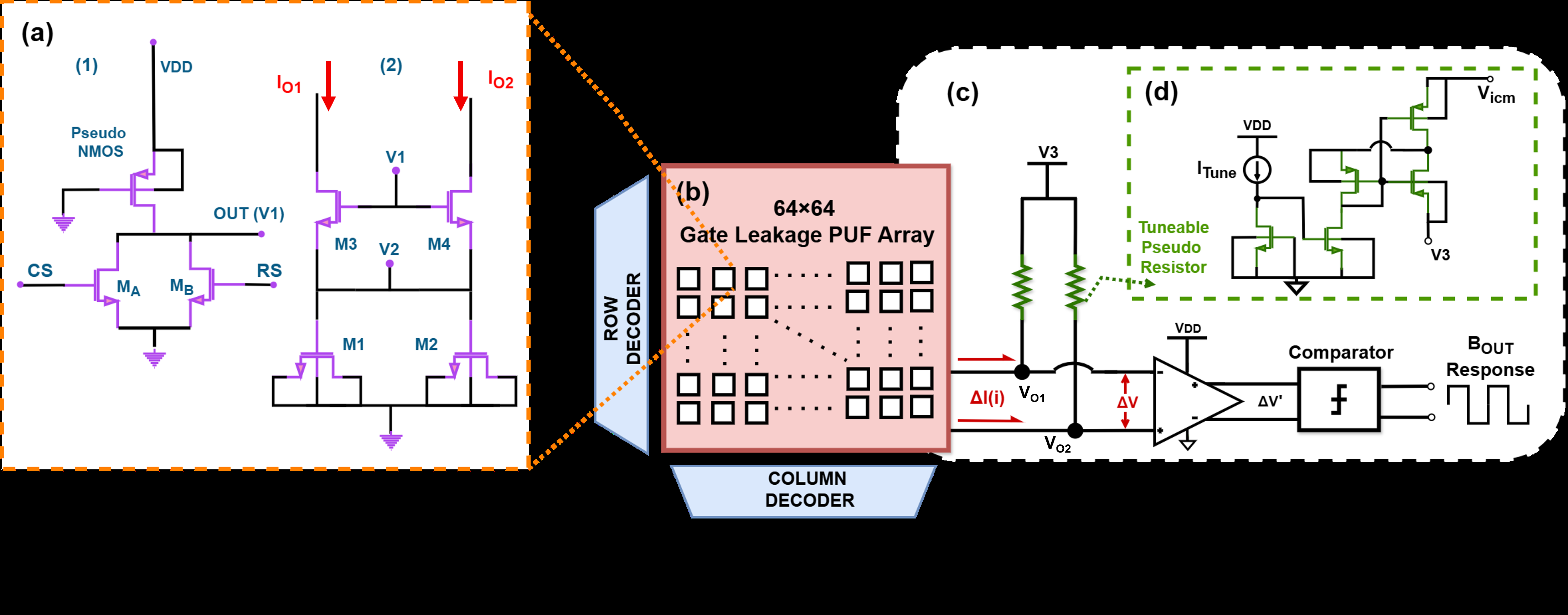
Fig 1: Schematic of QT-PUF system architecture composed of: (a-1) cell selection logic (CS and RS are the column and row select signals) and (a-2)
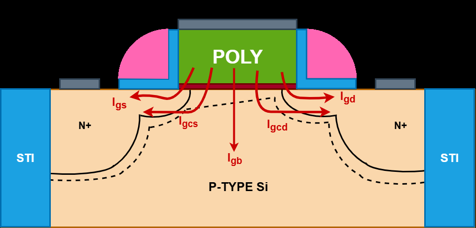
Fig 2: Schematic illustrating the five gate leakage components in NMOS
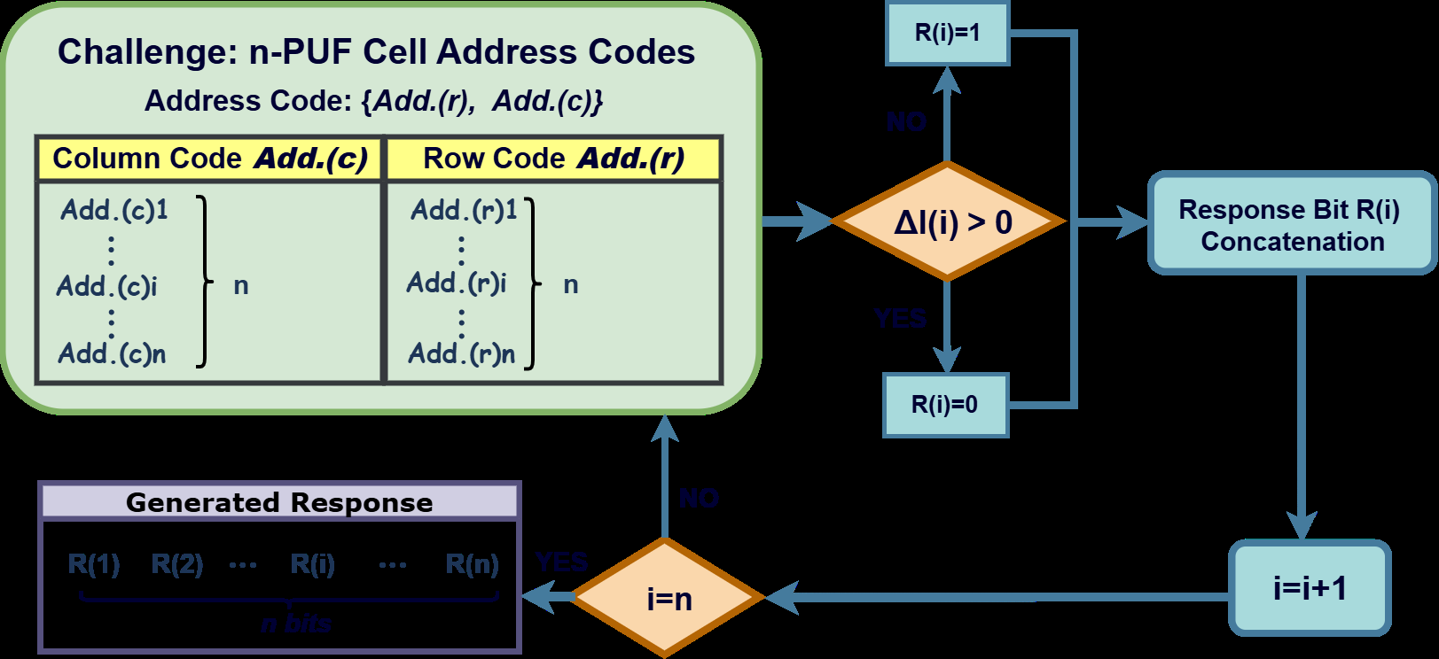
Fig 3: CRP generation workflow: a challenge with address and response
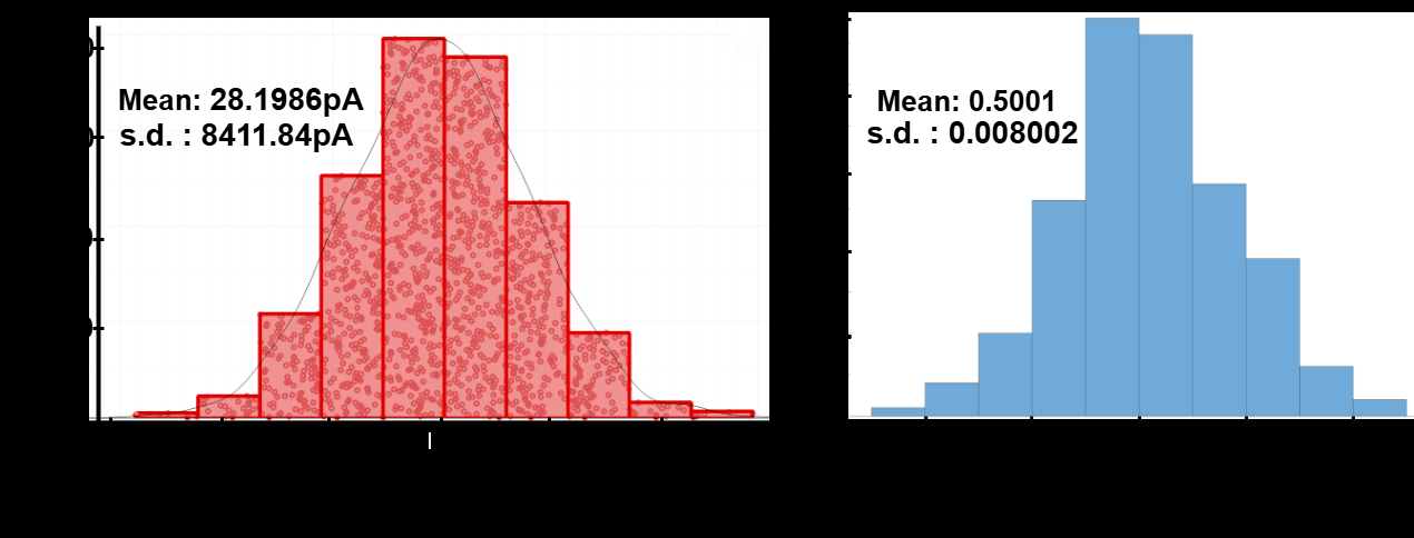
Fig 4: (a) Distribution of differential leakage currents: the mean value is
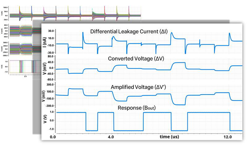
Fig 5: PUF waveforms of 1500 samples obtained from simulation with
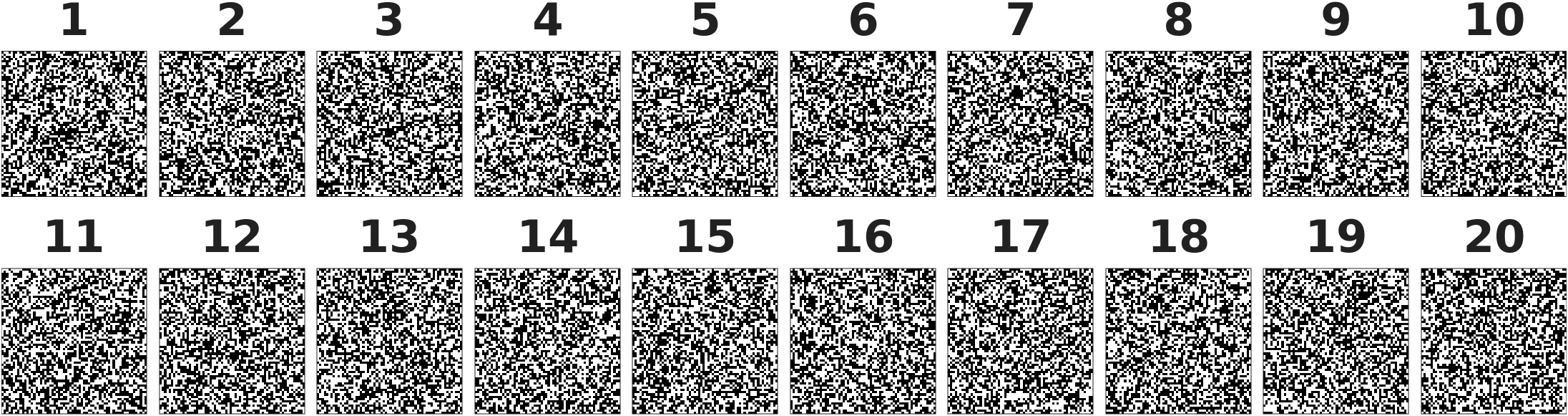
Fig 6: Logical speckle figure of measured PUF output from 20 arrays:
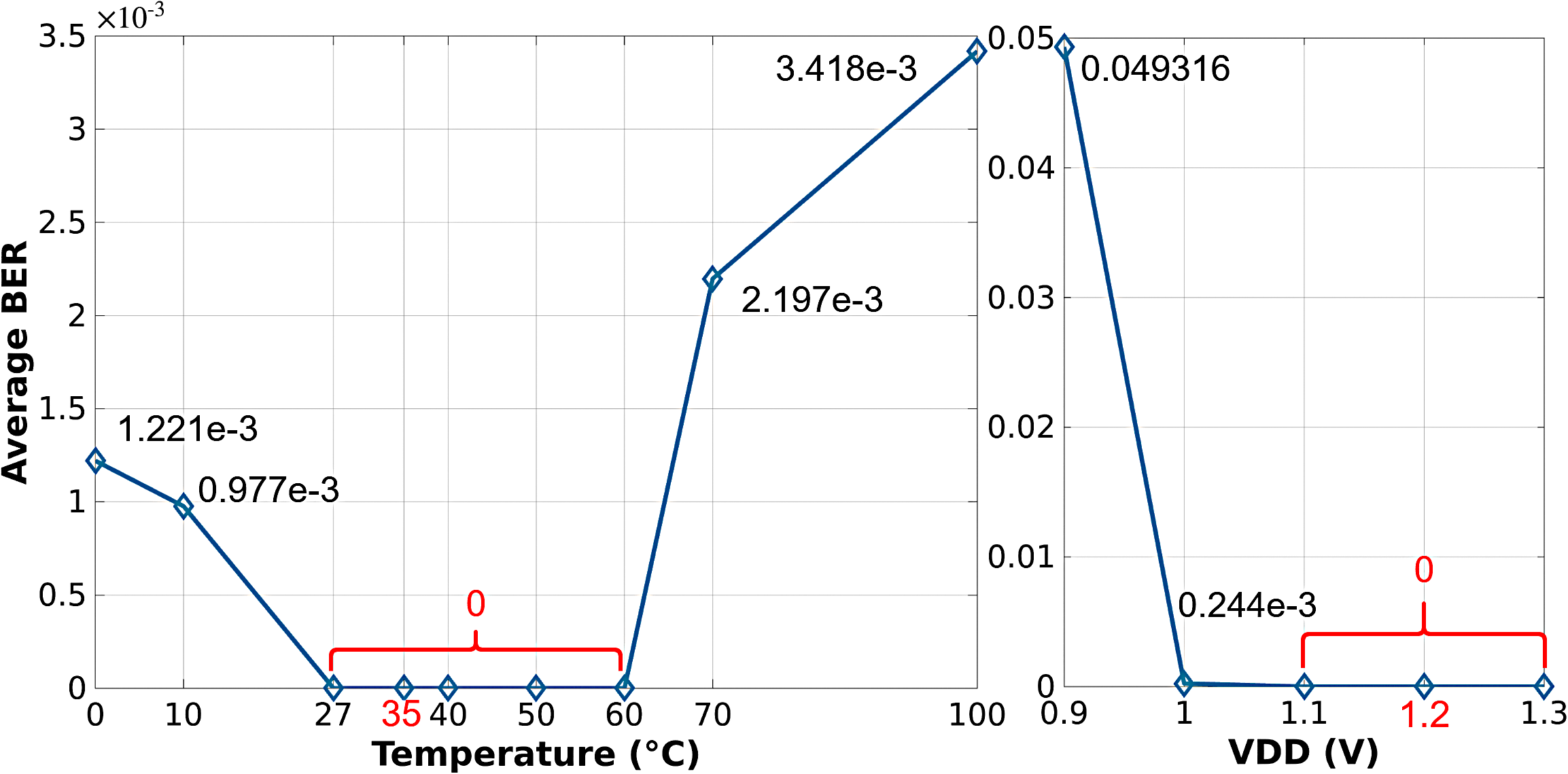
Fig 7: Measured BER of the proposed PUF under (a) temperature variation
Limitations
- Evaluations are simulation-based; no fabricated silicon measurements have been presented yet, so real-world effects might differ.
- Security robustness against invasive, side-channel, fault injection, and modeling attacks remains unexplored empirically.
- Long-term aging effects on gate leakage tunneling variability and reliability have not been experimentally characterized.
- Scalability to larger arrays beyond 64×64 and implications on area overhead and readout latency need investigation.
- The larger area per bit (9151.95 F2) compared to some SRAM or NAND PUFs may impact integration density.
- Assumes adversary cannot manipulate supply voltage or temperature beyond tested ranges; extreme environmental conditions not tested.
Open questions / follow-ons
- How does QT-PUF perform against adversarial modeling attacks such as machine learning or side-channel emulation?
- What is the impact of device aging and oxide degradation on long-term stability and uniqueness?
- Can the design be further miniaturized to reduce area overhead without sacrificing stability?
- How does hardware implementation (silicon measurement) compare to simulation results?
Why it matters for bot defense
For bot-defense and CAPTCHA practitioners, QT-PUF provides a promising approach for ultra-low-power, hardware-embedded uniqueness and authentication primitives. Its static operation without requiring dynamic stabilization or large power budgets makes it particularly suited for implantation or always-on IoMT devices where secure device identity is critical. The demonstrated high entropy and stability under voltage and temperature variations suggest it can provide robust hardware-rooted secrets to underpin challenge-response authentication protocols. However, further validation on silicon and adversarial resilience are needed before deployment. Integrating similar quantum tunneling leakage based PUFs could help CI/CD pipelines for IoMT device onboarding and continuous attestation against counterfeit or cloned devices, enhancing trust in sensitive healthcare contexts.
Cite
@article{arxiv2605_22113,
  title={ QT-PUF: Quantum Tunneling Leakage Based PUF for Implantable IoMT Devices },
  author={ Yueqi Ma and Vivek Mohan and Chip-Hong Chang and Emmanuel M. Drakakis },
  journal={arXiv preprint arXiv:2605.22113},
  year={ 2026 },
  url={https://arxiv.org/abs/2605.22113}
}